Dialogue Tech NANO-PV-D510A User Manual
Browse online or download User Manual for Motherboards Dialogue Tech NANO-PV-D510A. Dialogue Tech NANO-PV-D510A User's Manual
- Page / 169
- Table of contents
- BOOKMARKS
- NANO-PV-D510A 1
- Revision 2
- Copyright 3
- Table of Contents 4
- List of Figures 9
- List of Tables 12
- BIOS Menus 14
- 1 Introduction 15
- 1.1 Introduction 16
- 1.2 Features 16
- 1.3 Connectors 17
- 1.4 Dimensions 17
- 1.5 Data Flow 19
- 1.6 Technical Specifications 19
- 2 Unpacking 22
- 2.1 Anti-static Precautions 23
- 2.2 Unpacking Precautions 23
- 2.3 Packing List 24
- 2.3.1 Optional Items 25
- 3 Connectors 26
- Page 14 28
- Pin Description 29
- 1 Battery+ 31
- 2 Ground 31
- Page 18 32
- 3 FANIO1 34
- 3 GND 4 GND 35
- 7 HDD_LED- 8 GND 35
- Page 26 40
- 3.2.13 PCIe Mini Card Slot 40
- 1 VCC 2 GND 46
- 3 DATAN- 4 DATAM+ 46
- 5 DATAN+ 6 DATAM 46
- 7 GND 8 VCC 46
- 4 Installation 51
- 4.1 Anti-static Precautions 52
- WARNING: 53
- 4.3 Memory Installation 54
- NOTE: 56
- Setting Description 57
- Short Use AT power 57
- Open Use ATX power 57
- Short 1-2 RS-232 59
- Short 2-3 RS-422/RS-485 59
- Open Slave 60
- Closed Master 60
- 1-2 +3.3 V 61
- 3-4 +5.0 V 61
- 5-6 +12 V 61
- 4.5 Chassis Installation 63
- Page 52 66
- Page 54 68
- 6Figure 4-16 69
- Page 56 70
- Page 58 72
- 4.7.4 USB Connection 72
- 4.7.5 VGA Monitor Connection 73
- 4.8 Software Installation 74
- Chapter 76
- 5.1 Introduction 77
- 5.3 Advanced 80
- 5.3.1 CPU Configuration 81
- Configuration 82
- Page 70 84
- Page 82 96
- NANO-PV-D510A User Manual 105
- 5.3.7.1 AHCI Port n 105
- 5.4 PCI/PnP 110
- 5.5 Boot 113
- DEFAULT 115
- Page 102 116
- 5.5.2 Boot Device Priority 116
- 5.5.3 Hard Disk Drives 117
- Page 103 117
- 5.6 Security 119
- 5.7 Chipset 120
- Page 107 121
- Page 108 122
- 5.8 Exit 124
- Page 111 125
- A BIOS Options 126
- B One Key Recovery 130
- Page 119 133
- Page 121 135
- Page 122 136
- Page 124 138
- Page 126 140
- Page 127 141
- Page 129 143
- Page 130 144
- Page 132 146
- B.4 Recovery Tool Functions 147
- Formatted: Bulle 147
- Page 138 152
- B.4.4 Manual 152
- C Terminology 153
- Page 140 154
- Page 141 155
- Page 142 156
- D Digital I/O Interface 157
- D.1 Introduction 158
- D.2 DIO Connector Pinouts 158
- E Watchdog Timer 160
- Page 147 161
- F Compatibility 163
- Page 150 164
- Page 151 165
- G Hazardous Materials 166
- Disclosure 166
- Mercury 167
- Page 154 168
- Page 155 169
Summary of Contents
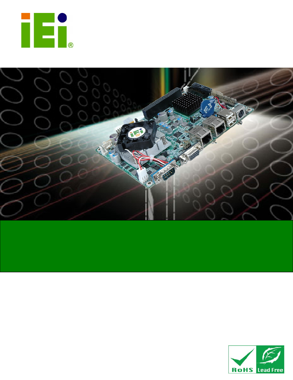
NANO-PV-D510A User Manual Page iIEI Technology Corp. User Manual NANO-PV-D510A MODEL: NANO-PV-D510A EPIC SBC with Intel® Atom™ D510 Dual Core Proces
NANO-PV-D510A User ManualPage x Figure 4-1: CompactFlash® Card Installation ...
NANO-PV-D510A User ManualPage 86 Boot Loader Redirection is active during POST and during Boot Loader Always DEFAULT Redirection is always act
NANO-PV-D510A User Manual Page 87BIOS SETUP UTILITY Main Advanced PCIPNP Boot Security Chipset Power Exit Select AT/ATX Power [BY HARDWARE] C
NANO-PV-D510A User ManualPage 88 BIOS SETUP UTILITY Main Advanced PCIPNP Boot Security Chipset Power Exit ACPI Settings ⎯⎯⎯⎯⎯⎯⎯⎯⎯⎯⎯⎯⎯⎯⎯⎯⎯⎯⎯⎯⎯⎯
NANO-PV-D510A User Manual Page 89 Resume on Keyboard/Mouse [Disabled] Use the Resume on Keyboard/Mouse BIOS option to enable activity on either th
NANO-PV-D510A User ManualPage 90 Disabled DEFAULT The real time clock (RTC) cannot generate a wake event Enabled If selected, the following app
NANO-PV-D510A User Manual Page 91BIOS SETUP UTILITY Main Advanced PCIPNP Boot Security Chipset Power Exit AHCI Settings ⎯⎯⎯⎯⎯⎯⎯⎯⎯⎯⎯⎯⎯⎯⎯⎯⎯⎯⎯⎯⎯⎯
NANO-PV-D510A User ManualPage 92 BIOS SETUP UTILITY Main Advanced PCIPNP Boot Security Chipset Power Exit AHCI Port0 ⎯⎯⎯⎯⎯⎯⎯⎯⎯⎯⎯⎯⎯⎯⎯⎯⎯⎯⎯⎯⎯⎯⎯⎯⎯
NANO-PV-D510A User Manual Page 93BIOS SETUP UTILITY Main Advanced PCIPNP Boot Security Chipset Exit USB Configuration ⎯⎯⎯⎯⎯⎯⎯⎯⎯⎯⎯⎯⎯⎯⎯⎯⎯⎯⎯⎯⎯⎯⎯
NANO-PV-D510A User ManualPage 94 Disabled USB 2.0 controller disabled Enabled DEFAULT USB 2.0 controller enabled Legacy USB Support [Enabled
NANO-PV-D510A User Manual Page 95BIOS SETUP UTILITY Main Advanced PCIPNP Boot Security Chipset Power Exit USB Mass Storage Device Configuratio
NANO-PV-D510A User Manual Page xiFigure B-14: Compress Image... Error! Bookmark not defined.
NANO-PV-D510A User ManualPage 96 Auto DEFAULT BIOS auto-detects the current USB. Floppy The USB device will be emulated as a floppy drive. The
NANO-PV-D510A User Manual Page 97BIOS SETUP UTILITY Main Advanced PCIPNP Boot Security Chipset Exit Advanced PCI/PnP Settings ⎯⎯⎯⎯⎯⎯⎯⎯⎯⎯⎯⎯⎯⎯⎯
NANO-PV-D510A User ManualPage 98 IRQ9 IRQ10 IRQ 11 IRQ 14 IRQ 15 DMA Channel# [Available] Use the DMA Channel# option to assign a speci
NANO-PV-D510A User Manual Page 995.5 Boot Use the Boot menu (BIOS Menu 16) to configure system boot options. BIOS SETUP UTILITY Main Advanced PCIP
NANO-PV-D510A User ManualPage 100 Quick Boot [Enabled] Use the Quick Boot BIOS option to make the computer speed up the boot process. Disabled
NANO-PV-D510A User Manual Page 101 Bootup Num-Lock [On] Use the Bootup Num-Lock BIOS option to specify if the number lock setting must be modified
NANO-PV-D510A User ManualPage 102 5.5.2 Boot Device Priority Use the Boot Device Priority menu (BIOS Menu 18) to specify the boot sequence from the
NANO-PV-D510A User Manual Page 1035.5.3 Hard Disk Drives Use the Hard Disk Drives menu to specify the boot sequence of the available HDDs. Only inst
NANO-PV-D510A User ManualPage 104 5.5.4 Removable Drives Use the Removable Drives menu (BIOS Menu 20) to specify the boot sequence of the removable
NANO-PV-D510A User Manual Page 105The boot sequence from the available devices is selected. If the “1st Drive” option is selected a list of availabl
NANO-PV-D510A User ManualPage xii List of Tables Table 1-1: Technical Specifications...
NANO-PV-D510A User ManualPage 106 Change Supervisor Password Use the Change Supervisor Password to set or change a supervisor password. The defau
NANO-PV-D510A User Manual Page 107BIOS SETUP UTILITY Main Advanced PCIPNP Boot Security Chipset Exit Advanced Chipset Settings ⎯⎯⎯⎯⎯⎯⎯⎯⎯⎯⎯⎯⎯⎯
NANO-PV-D510A User ManualPage 108 Initiate Graphic Adapter Use the Initiate Graphic Adapter option to select the graphics controller used as the
NANO-PV-D510A User Manual Page 1095.7.2 Southbridge Configuration Use the Southbridge Configuration menu (BIOS Menu 25) to configure the Southbridge
NANO-PV-D510A User ManualPage 110 5.8 Exit Use the Exit menu (BIOS Menu 26) to load default BIOS values, optimal failsafe values and to save configu
NANO-PV-D510A User Manual Page 111 Load Failsafe Defaults Use the Load Failsafe Defaults option to load failsafe default values for each of the pa
NANO-PV-D510A User ManualPage 112 Appendix A A BIOS Options
NANO-PV-D510A User Manual Page 113Below is a list of BIOS configuration options in the BIOS chapter. System Overview ...
NANO-PV-D510A User ManualPage 114 CPU Fan Fourth Setting [060]...
NANO-PV-D510A User Manual Page 115 AddOn ROM Display Mode [Force BIOS] ... 100
NANO-PV-D510A User Manual Page xiiiTable 4-3: AT/ATX Power Select Jumper Settings...
NANO-PV-D510A User ManualPage 116 Appendix B B One Key Recovery
NANO-PV-D510A User Manual Page 117B.1 One Key Recovery Introduction The IEI one key recovery is an easy-to-use front end for the Norton Ghost system
NANO-PV-D510A User ManualPage 118 o Windows 7 o Windows CE 5.0 o Windows CE 6.0 o Windows XP Embedded Linux o Fedora Core 12 (Constantine) o
NANO-PV-D510A User Manual Page 119 NOTE: The recovery CD can only be used with IEI products. The software will fail to run and a warning message wil
NANO-PV-D510A User ManualPage 120 NOTE: The setup procedures described below are for Microsoft Windows operating system users. For Linux system, mo
NANO-PV-D510A User Manual Page 121 Figure B-1: Recovery Tool Setup Menu Step 5: Press <5> then <Enter>. Figure B-2: Command Mode Step
NANO-PV-D510A User ManualPage 122 Figure B-3: Partition Creation Commands
NANO-PV-D510A User Manual Page 123 NOTE: Use the following commands to check if the partitions were created successfully. Step 7: Press any key to
NANO-PV-D510A User ManualPage 124 Step 2: Start the system. Step 3: Press any key to boot from the recovery CD. It will take a while to launch the
NANO-PV-D510A User Manual Page 125Step 6: After completing the system configuration, press any key in the following window to reboot the system. F
NANO-PV-D510A User ManualPage xiv BIOS Menus BIOS Menu 1: Main ...
NANO-PV-D510A User ManualPage 126 Figure B-8: Recovery Tool Menu Step 3: The About Symantec Ghost window appears. Click OK button to continue. Fi
NANO-PV-D510A User Manual Page 127 Figure B-10: Symantec Ghost Path Step 5: Select the local source drive as shown in Figure B-11. Then click OK.
NANO-PV-D510A User ManualPage 128 Step 7: Select 1.2: [Recovery] NTFS drive and enter a file name called iei (Figure B-13). Click Save. The factory
NANO-PV-D510A User Manual Page 129Step 8: When the Compress Image screen in Figure B-14 prompts, click High to make the image file smaller. Figure
NANO-PV-D510A User ManualPage 130 Step 11: When the image creation completes, a screen prompts as shown in Figure B-17. Click Continue and close the
NANO-PV-D510A User Manual Page 131 NOTE: If the Linux OS is not installed with GRUB (v0.97 or earlier) and Ext3, the Symantec Ghost may not function
NANO-PV-D510A User ManualPage 132 system32>format N: /fs:ntfs /q /v:Recovery /y system32>exit Step 4: Build-up recovery partition. Press any
NANO-PV-D510A User Manual Page 133 Step 7: The recovery tool menu appears. (Figure B-22) Figure B-22: Recovery Tool Menu Step 8: Create a factory
NANO-PV-D510A User ManualPage 134 Figure B-23: Recovery Tool Main Menu The recovery tool has several functions including: 1. Factory Restore: Resto
NANO-PV-D510A User Manual Page 135B.4.1 Factory Restore To restore the factory default image, please follow the steps below. Step 9: Type <1>
NANO-PV-D510A User Manual Page 1Chapter 1 1 Introduction
NANO-PV-D510A User ManualPage 136 B.4.2 Backup System To backup the system, please follow the steps below. Step 12: Type <2> and press <Ent
NANO-PV-D510A User Manual Page 137B.4.3 Restore Your Last Backup To restore the last system backup, please follow the steps below. Step 15: Type <
NANO-PV-D510A User ManualPage 138 B.4.4 Manual To restore the last system backup, please follow the steps below. Step 18: Type <4> and press &
NANO-PV-D510A User Manual Page 139Appendix C C Terminology
NANO-PV-D510A User ManualPage 140 AC ’97 Audio Codec 97 (AC’97) refers to a codec standard developed by Intel® in 1997. ACPI Advanced Configuration
NANO-PV-D510A User Manual Page 141DMA Direct Memory Access (DMA) enables some peripheral devices to bypass the system processor and communicate dire
NANO-PV-D510A User ManualPage 142 LCD Liquid crystal display (LCD) is a flat, low-power display device that consists of two polarizing plates with a
NANO-PV-D510A User Manual Page 143Appendix D D Digital I/O Interface
NANO-PV-D510A User ManualPage 144 D.1 Introduction The DIO connector on the NANO-PV-D510A is interfaced to GPIO ports on the Super I/O chipset. The
NANO-PV-D510A User Manual Page 145D.3 Assembly Language Samples D.3.1 Enable the DIO Input Function The BIOS interrupt call INT 15H controls the dig
NANO-PV-D510A User ManualPage 2 1.1 Introduction Figure 1-1: NANO-PV-D510A The NANO-PV-D510A EPIC CPU card is an embedded 45 nm Intel® Atom™ proces
NANO-PV-D510A User ManualPage 146 Appendix E E Watchdog Timer
NANO-PV-D510A User Manual Page 147 NOTE: The following discussion applies to DOS. Contact IEI support or visit the IEI website for drivers for other
NANO-PV-D510A User ManualPage 148 NOTE: The Watchdog Timer is activated through software. The software application that activates the Watchdog Time
NANO-PV-D510A User Manual Page 149Appendix F F Compatibility
NANO-PV-D510A User ManualPage 150 NOTE: The compatible items described here have been tested by the IEI R&D team and found to be compatible wit
NANO-PV-D510A User Manual Page 151F.2 Compatible Memory Modules NOTE: The memory modules listed below have been tested on the NANO-PV-D510A other m
NANO-PV-D510A User ManualPage 152 Appendix G G Hazardous Materials Disclosure
NANO-PV-D510A User Manual Page 153G.1 Hazardous Materials Disclosure Table for IPB Products Certified as RoHS Compliant Under 2002/95/EC Without Mer
NANO-PV-D510A User ManualPage 154 Toxic or Hazardous Substances and Elements Part Name Lead (Pb) Mercury (Hg) Cadmium(Cd) Hexavalent Chromium(CR(VI)
NANO-PV-D510A User Manual Page 155此附件旨在确保本产品符合中国 RoHS 标准。以下表格标示此产品中某有毒物质的含量符合中国 RoHS 标准规定的限量要求。 本产品上会附有”环境友好使用期限”的标签,此期限是估算这些物质”不会有泄漏或突变”的年限。本产品可能包含
NANO-PV-D510A User Manual Page 31.3 Connectors The connectors on the NANO-PV-D510A are shown in the figure below. Figure 1-2: Connectors 1.4 Dimen
NANO-PV-D510A User ManualPage 4 Figure 1-3: NANO-PV-D510A Dimensions (mm)
NANO-PV-D510A User Manual Page 51.5 Data Flow 6Figure 1-4 shows the data flow between the system chipset, the CPU and other components installed on
NANO-PV-D510A User ManualPage ii Revision Date Version Changes 25 May, 2010 1.00 Initial release
NANO-PV-D510A User ManualPage 6 Specification NANO-PV-D510A Memory One single-channel 2.0 GB (max.) 667/800 MHz DDR2 SDRAM SO-DIMM supported Audio
NANO-PV-D510A User Manual Page 7Specification NANO-PV-D510A Environmental and Power Specifications Power Supply 12 V only, AT/ATX support by jumper
NANO-PV-D510A User ManualPage 8 Chapter 2 2 Unpacking
NANO-PV-D510A User Manual Page 92.1 Anti-static Precautions WARNING! Static electricity can destroy certain electronics. Make sure to follow the ES
NANO-PV-D510A User ManualPage 10 2.3 Packing List NOTE: If any of the components listed in the checklist below are missing, do not proceed with the
NANO-PV-D510A User Manual Page 111 Utility CD 1 Quick Installation Guide 2.3.1 Optional Items The NANO-PV-D510A is shipped with the following com
NANO-PV-D510A User ManualPage 12 Chapter 3 3 Connectors
NANO-PV-D510A User Manual Page 133.1 Peripheral Interface Connectors This chapter details all the jumpers and connectors. 3.1.1 Layout The figures b
NANO-PV-D510A User ManualPage 14 Connector Type Label +12 V ATX power supply connector 4-pin ATX connector CPU12V1 Audio connector 10-pin header
NANO-PV-D510A User Manual Page 15Connector Type Label Ethernet connector RJ-45 LAN1, LAN2 Keyboard/Mouse connector PS/2 PT1 RS-232 serial port
NANO-PV-D510A User Manual Page iiiCopyright COPYRIGHT NOTICE The information in this document is subject to change without prior notice in order to
NANO-PV-D510A User ManualPage 16 Pin Description 3 EXT_12VIN 4 EXT_12VIN Table 3-3: AT Power Connector Pinouts 3.2.2 Audio Kit Connector CN Label:
NANO-PV-D510A User Manual Page 173.2.3 Battery Connector CN Label: BAT1 CN Type: 2-pin wafer (1x2) CN Location: See Figure 3-5 CN Pinouts: See Tabl
NANO-PV-D510A User ManualPage 18 Figure 3-6: CompactFlash® Slot Location Pin Description Pin Description 1 GROUND 26 VCC-IN CHECK1 2 DATA 3 27
NANO-PV-D510A User Manual Page 19Pin Description Pin Description 23 DATA 2 48 DATA 9 24 N/C 49 DATA 10 25 VCC-IN CHECK2 50 GROUND Table 3-6: Compa
NANO-PV-D510A User ManualPage 20 3.2.6 Fan Connector CN Label: CPU_FAN1, SYS_FAN1 CN Type: 3-pin header CN Location: See Figure 3-8 CN Pinouts: See
NANO-PV-D510A User Manual Page 21The front panel connector connects to the indicator LEDs and buttons on the computer's front panel. Figure 3-
NANO-PV-D510A User ManualPage 22 Figure 3-10: Backlight Inverter Connector Location Pin Description 1 BACKLIGHT ADJUST 2 GROUND 3 +12 V 4 GROUND 5
NANO-PV-D510A User Manual Page 23Pin Description 1 +5 V KB DATA 2 MS DATA 3 MS CLK 4 KB DATA 5 KB CLK 6 GROUND Table 3-11: Keyboard/Mouse Connector
NANO-PV-D510A User ManualPage 24 Pin Description Pin Description 13 GROUND 14 GROUND 15 LDDC_DATA 16 LDDC_CLK 17 VCC_LCD 18 VCC_LCD 19 VCC_LCD 20 V
NANO-PV-D510A User Manual Page 25Pin Description Pin Description 19 GROUND 20 GROUND 21 GROUND 22 GROUND 23 GROUND 24 GROUND 25 GROUND 26 NC Ta
NANO-PV-D510A User ManualPage iv Table of Contents 1 INTRODUCTION...
NANO-PV-D510A User ManualPage 26 Pin Row A Row B Row C Row D 9 SERR# GND SB0# PAR 10 GND PERR# +3.3 V SDONE 11 STOP# +3.3 V LOCK# GND 12 +3.3
NANO-PV-D510A User Manual Page 27 Figure 3-15: PCIe Mini Card Slot Location Pin Description Pin Description 1 PCIE_WAKE# 2 VCC3 3 N/C 4 GND 5 N
NANO-PV-D510A User ManualPage 28 Pin Description Pin Description 47 SATA_TXP1 48 1.5 V 49 GND 50 GND 51 N/C 52 VCC3 Table 3-15: PCIe Mini Card
NANO-PV-D510A User Manual Page 293.2.15 SATA Power Connector CN Label: PWR1 CN Type: 2-pin header CN Location: See Figure 3-17 CN Pinouts: See Tabl
NANO-PV-D510A User ManualPage 30 Figure 3-18: Serial Port Connector Locations Pin Description Pin Description 1 Data Carrier Direct (DCD) 2 Da
NANO-PV-D510A User Manual Page 31Pin Description Pin Description 1 DCD 2 NDSR2 3 RXD 4 NRTS2 5 TXD 6 NCTS2 7 DTR 8 NRI2 9 GND 10 GND 11
NANO-PV-D510A User ManualPage 32 3.2.19 USB Connector CN Label: USB0_1, USB2_3 and USB4_5 CN Type: 8-pin header (2x4) CN Location: See Figure 3-21
NANO-PV-D510A User Manual Page 33 Figure 3-22: External Peripheral Interface Connector 3.3.1 Keyboard/Mouse Connector CN Label: PT1 CN Type: PS/2
NANO-PV-D510A User ManualPage 34 3.3.2 LAN Connector CN Label: LAN1 CN Type: RJ-45 CN Location: See Figure 3-24 CN Pinouts: See Table 3-23 A 10/100
NANO-PV-D510A User Manual Page 353.3.3 Serial Port Connectors (COM1) CN Label: COM1 CN Type: DB-9 connector CN Location: See Figure 3-22 CN Pinouts
NANO-PV-D510A User Manual Page v3.2.12 PCI-104 Connector... 25
NANO-PV-D510A User ManualPage 36 Pin Description Pin Description 1 USBV3L 5 V 2 GND 3 USBP4N 4 USBP5P 5 USBP4P 6 USBP5N 7 GND 8 USBV3L 5 V Table
NANO-PV-D510A User Manual Page 37Chapter 4 4 Installation
NANO-PV-D510A User ManualPage 38 4.1 Anti-static Precautions WARNING: Failure to take ESD precautions during the installation of the NANO-PV-D510A
NANO-PV-D510A User Manual Page 39 WARNING: The installation instructions described in this manual should be carefully followed in order to prevent d
NANO-PV-D510A User ManualPage 40 4.3 Memory Installation WARNING: Do not run the CPU without a heatsink and fan. Without the heatsink and fan, the
NANO-PV-D510A User Manual Page 41 Figure 4-1: CompactFlash® Card Installation 4.3.2 PCIe Mini Card Installation To install the PCIe Mini card, pleas
NANO-PV-D510A User ManualPage 42 Step 4: Insert into the socket at and angle. Line up the notch on the card with the notch on the connector. Slide
NANO-PV-D510A User Manual Page 43Description Label Type AT/ATX power select J_AUTOPWR1 2-pin headerAT/ATX power select J_ATXCTL1 3-pin headerCo
NANO-PV-D510A User ManualPage 44 4.4.2 AT/ATX Power Select Jumper Settings Jumper Label: J_ATXCTL1 Jumper Type: 3-pin header Jumper Settings: See T
NANO-PV-D510A User Manual Page 45 Figure 4-5: Clear BIOS Jumper Location 4.4.4 COM 3 Function Select Jumper Jumper Label: J1 Jumper Type: 3-pin hea
NANO-PV-D510A User ManualPage vi 4.6.2 Audio Cable Installation... 51
NANO-PV-D510A User ManualPage 46 The CompactFlash® slot is connected through an IDE connection. This jumper sets the CompactFlash® card as the maste
NANO-PV-D510A User Manual Page 47Setting Description 1-2 +3.3 V 3-4 +5.0 V 5-6 +12 V Table 4-7: LVDS Voltage Selection Jumper Settings Figure 4-
NANO-PV-D510A User ManualPage 48 Pin Description Open 640 x 480 (18-bit) Short 1-2 800 x 480 (18-bit) Short 3-4 800 x 600 (18-bit) Short 1-2 and
NANO-PV-D510A User Manual Page 49 Figure 4-10: PCI-104 Voltage Jumper Location 4.5 Chassis Installation 4.5.1 Airflow WARNING: Airflow is critical
NANO-PV-D510A User ManualPage 50 4.6.1 AT/ATX Power Connection Follow the instructions below to connect the NANO-PV-D510A to an AT or ATX power supp
NANO-PV-D510A User Manual Page 51Step 3: Connect Power Cable to Power Supply. Connect one of the 4-pin (1x4) Molex type power cable connectors to a
NANO-PV-D510A User ManualPage 52 Step 5: Align pin 1. Align pin 1 on the on-board connector with pin 1 on the audio kit connector. Pin 1 on the aud
NANO-PV-D510A User Manual Page 53Step 6: Locate the connector. The location of the keyboard/mouse Y-cable connector is shown in Chapter 3. Step 7:
NANO-PV-D510A User ManualPage 54 PS/2 connectors. The keyboard PS/2 connector and mouse PS/2 connector are both marked. Please make sure the keyboar
NANO-PV-D510A User Manual Page 55Step 4: Connect the serial device. Once the single RS-232 connector is connected to a chassis or bracket, a serial
NANO-PV-D510A User Manual Page vii5.5.2 Boot Device Priority ...
NANO-PV-D510A User ManualPage 56 Figure 4-16: LAN Connection Step 3: Insert the LAN cable RJ-45 connector. Once aligned, gently insert the LAN cab
NANO-PV-D510A User Manual Page 57 Figure 4-17: PS/2 Keyboard/Mouse Connector Step 3: Connect the keyboard and mouse. Connect the keyboard and mouse
NANO-PV-D510A User ManualPage 58 Figure 4-18: Serial Device Connector Step 3: Secure the connector. Secure the serial device connector to the exte
NANO-PV-D510A User Manual Page 59 Figure 4-19: USB Connector 4.7.5 VGA Monitor Connection The NANO-PV-D510A has a single female DB-15 connector on t
NANO-PV-D510A User ManualPage 60 Figure 4-20: VGA Connector Step 6: Secure the connector. Secure the DB-15 VGA connector from the VGA monitor to t
NANO-PV-D510A User Manual Page 61 Figure 4-21: Introduction Screen Step 3: Click NANO-PV-D510A. Step 4: A new screen with a list of available driv
NANO-PV-D510A User ManualPage 62 Chapter 5 5 BIOS
NANO-PV-D510A User Manual Page 635.1 Introduction The BIOS is programmed onto the BIOS chip. The BIOS setup program allows changes to certain system
NANO-PV-D510A User ManualPage 64 Key Function F2 /F3 key Change color from total 16 colors. F2 to select color forward. F10 key Save all the C
NANO-PV-D510A User Manual Page 655.2 Main The Main BIOS menu (BIOS Menu 1) appears when the BIOS Setup program is entered. The Main menu gives an ov
NANO-PV-D510A User ManualPage viii D.3.2 Enable the DIO Output Function... 145 E WATC
NANO-PV-D510A User ManualPage 66 The System Overview field also has two user configurable fields: System Time [xx:xx:xx] Use the System Time opti
NANO-PV-D510A User Manual Page 67BIOS SETUP UTILITY Main Advanced PCIPNP Boot Security Chipset Exit Advanced Settings ⎯⎯⎯⎯⎯⎯⎯⎯⎯⎯⎯⎯⎯⎯⎯⎯⎯⎯⎯⎯⎯⎯⎯
NANO-PV-D510A User ManualPage 68 Frequency: Lists the CPU processing speed FSB Speed: Lists the FSB speed Cache L1: Lists the CPU L1 cache
NANO-PV-D510A User Manual Page 69 Enhanced DEFAULT Configures the on-board ATA/IDE controller to be in Enhanced mode. In this mode, IDE channels an
NANO-PV-D510A User ManualPage 70 BIOS SETUP UTILITY Main Advanced PCIPNP Boot Security Chipset Exit Primary IDE Master ⎯⎯⎯⎯⎯⎯⎯⎯⎯⎯⎯⎯⎯⎯⎯⎯⎯⎯⎯⎯⎯⎯
NANO-PV-D510A User Manual Page 71 32Bit Data Transfer: Enables 32-bit data transfer. Type [Auto] Use the Type BIOS option select the type of de
NANO-PV-D510A User ManualPage 72 Block (Multi Sector Transfer) [Auto] Use the Block (Multi Sector Transfer) to disable or enable BIOS to auto det
NANO-PV-D510A User Manual Page 73 Auto DEFAULT BIOS auto detects the DMA mode. Use this value if the IDE disk drive support cannot be determined.
NANO-PV-D510A User ManualPage 74 S.M.A.R.T [Auto] Use the S.M.A.R.T option to auto-detect, disable or enable Self-Monitoring Analysis and Reporti
NANO-PV-D510A User Manual Page 75 Serial Port1 Address [3F8] Use the Serial Port1 Address option to select the Serial Port 1 base address. Disab
NANO-PV-D510A User Manual Page ixList of Figures Figure 1-1: NANO-PV-D510A ...
NANO-PV-D510A User ManualPage 76 Serial Port3 Address [2F8] Use the Serial Port3 Address option to select the Serial Port 3 base address. Disab
NANO-PV-D510A User Manual Page 77 Parallel Port Address [Disabled] Use the Parallel Port Address option to select the parallel port base address.
NANO-PV-D510A User ManualPage 78 EPP+ECP The parallel port operates in the extended capabilities port (ECP) mode. The ECP mode supports bi-direct
NANO-PV-D510A User Manual Page 795.3.4 Hardware Health Configuration The Hardware Health Configuration menu (BIOS Menu 7) shows the operating tempe
NANO-PV-D510A User ManualPage 80 Auto Fan by RPM DEFAULT The fan adjusts its speed using these settings by RPM: CPU Temp. Highest Limit CPU T
NANO-PV-D510A User Manual Page 81 NOTE: PWM functions are supported only when using a 4-pin fan. When using a 3-pin fan, the PWM functions are not
NANO-PV-D510A User ManualPage 82 When the fan is off, it will only start when the temperature exceeds this setting. Minimum Value: 0°C Maximum
NANO-PV-D510A User Manual Page 83 CPU Fan Fourth Setting [060] This value is always full speed and corresponds to the CPU Temp. Fourth Limit. M
NANO-PV-D510A User ManualPage 84 allows a remote host running a terminal program to display and configure the BIOS settings. BIOS SETUP UTILITY Main
NANO-PV-D510A User Manual Page 85 Serial Port Number [COM1] Use the Serial Port Number option to select the serial port used for remote access.
© 2020, manymanuals.com. All rights reserved. | 1.034 s |
 Manymanuals.com
 Manymanuals.de
 Manymanuals.fr
 Manymanuals.it
 Manymanuals.pl
 Manymanuals.cz
 Manymanuals.es
 Manymanuals-pt.com
Comments to this Manuals